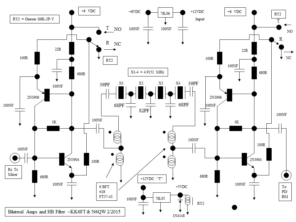
From Steve, (G0FUW) Here is a slick trick to pick the 4 crystals for the Part II Crystal Filter. My favourite method of grouping crystals is to use PSK31 software, Digipan or FLDigi are free and allow you to see the working frequency. Just set the rx to the xtal frequency and set the test oscillator going and log the software trace frequency, number or letter the rock and do the rest. Especially useful for those who are tone deaf! de G0FUW. Tnx Steve.
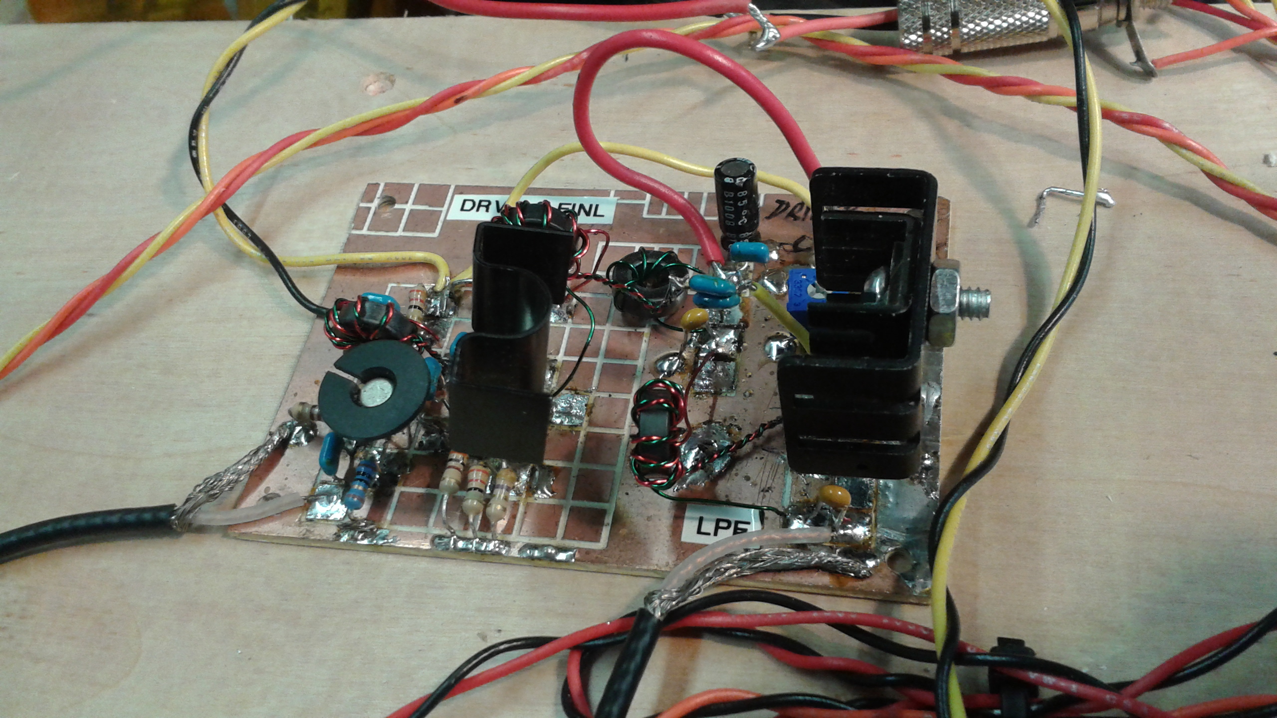
Revison 3/26/2015 See Driver /Final Schematic
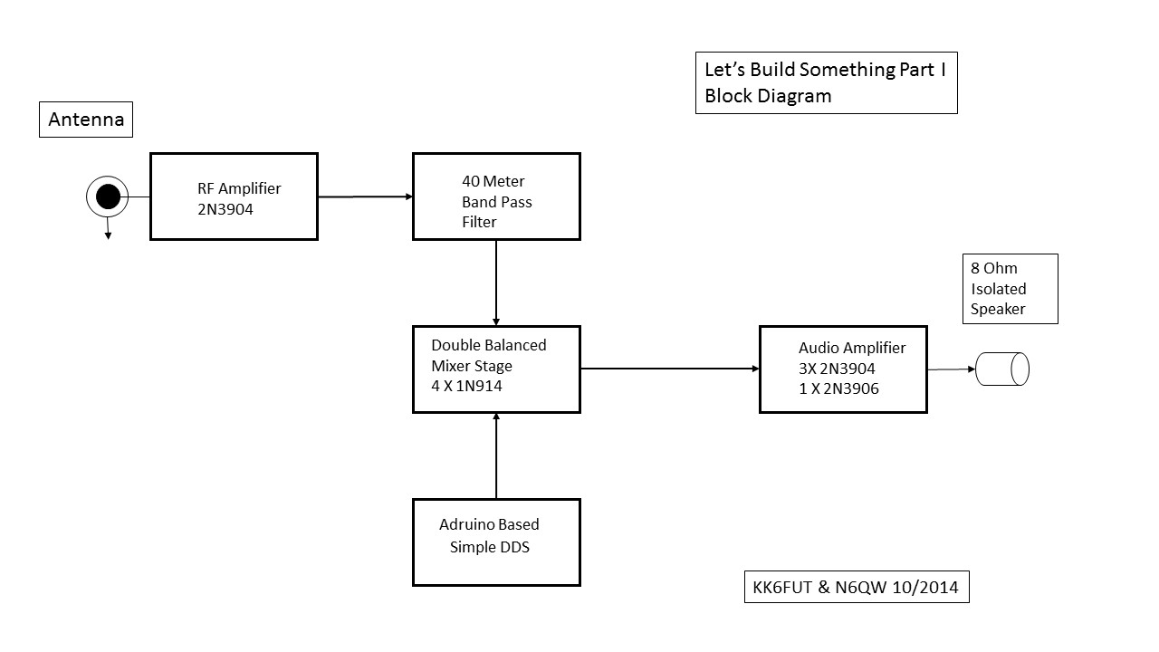
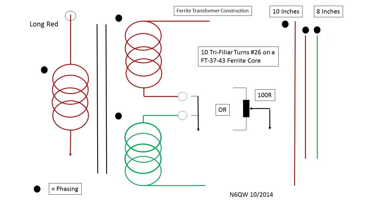
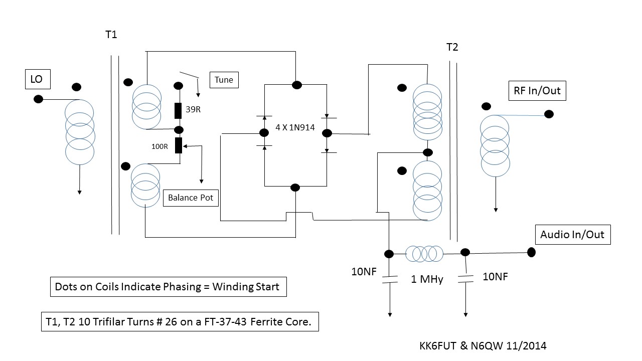
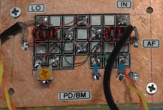
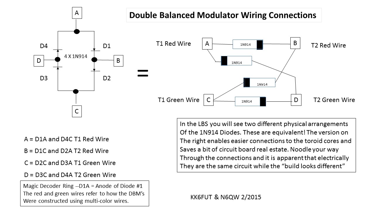
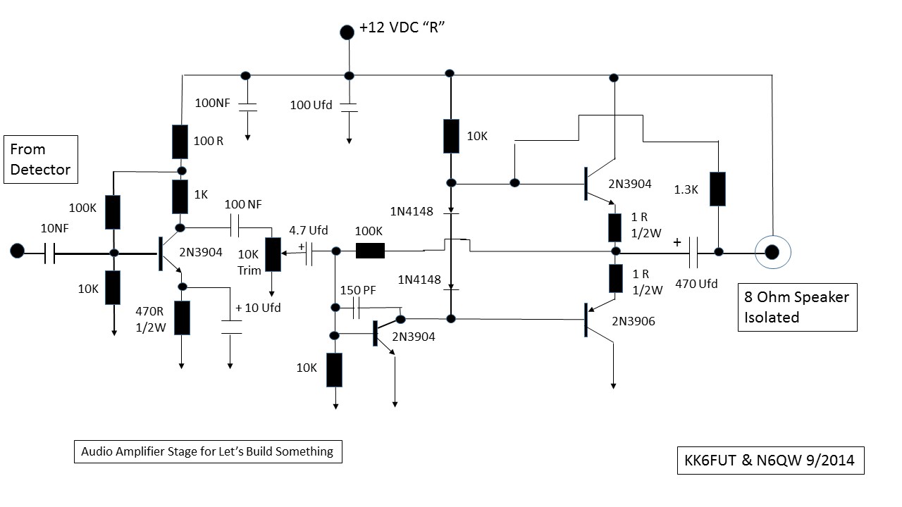
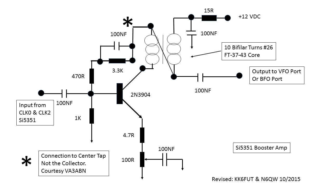
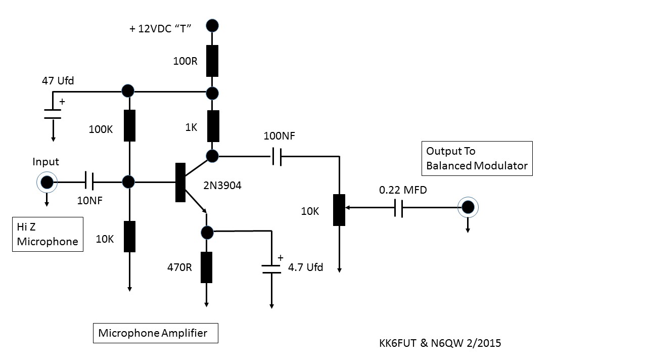
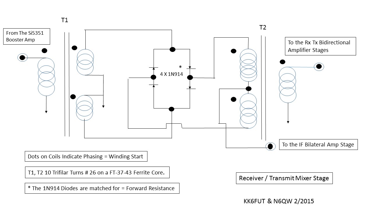
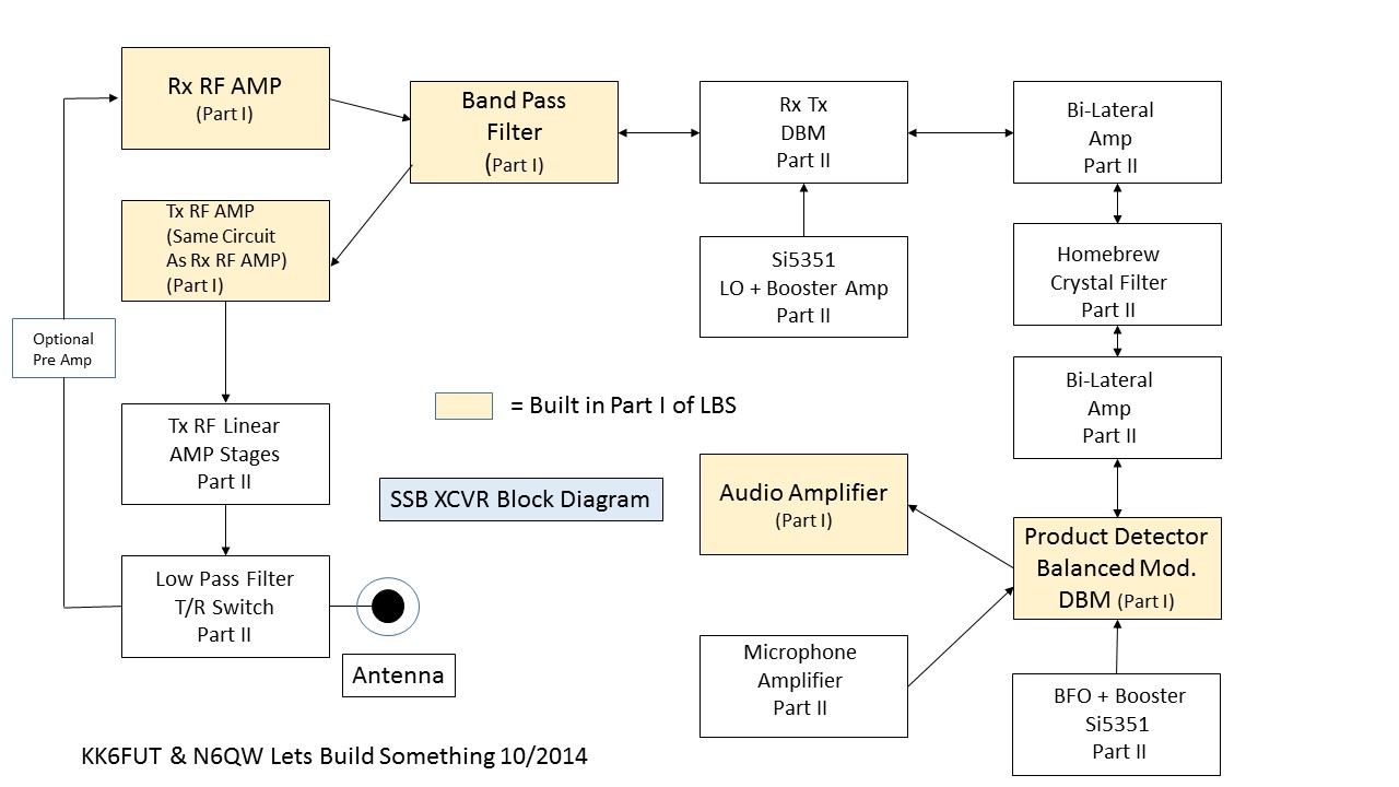
Fig 1 Block Diagram (Original) * Fig 1 Block Diagram Revision 1 * Ferrite Core Transformer Winding * Double Balanced Mixer Schematic Link to Photo ----------------------------Link to Photo * Audio Amplifier Schematic R1
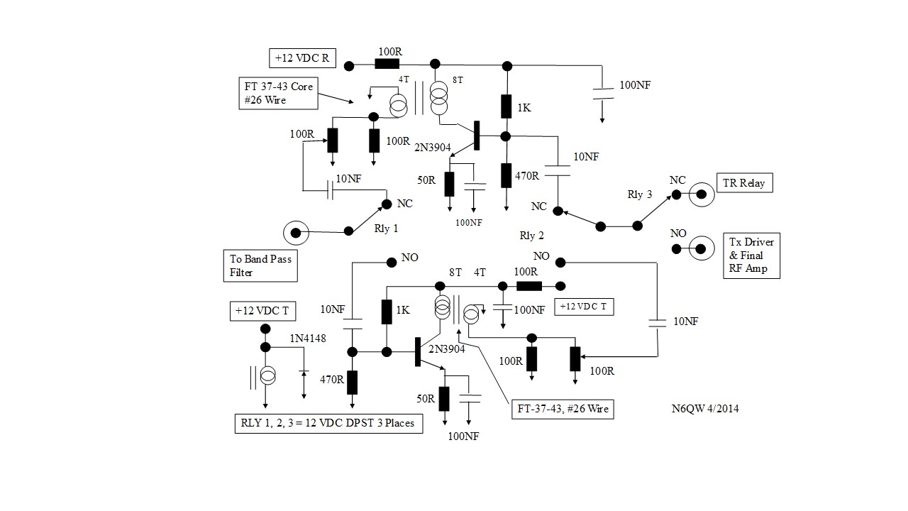
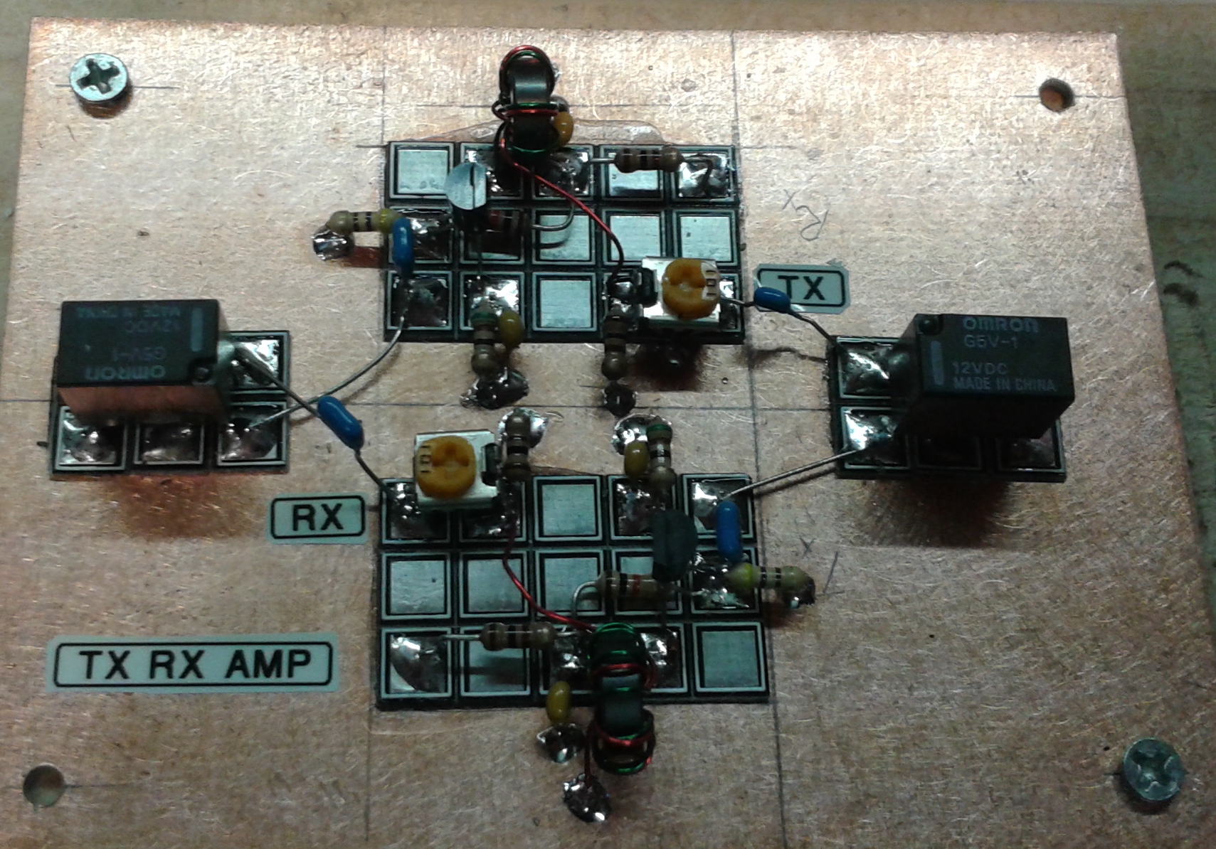
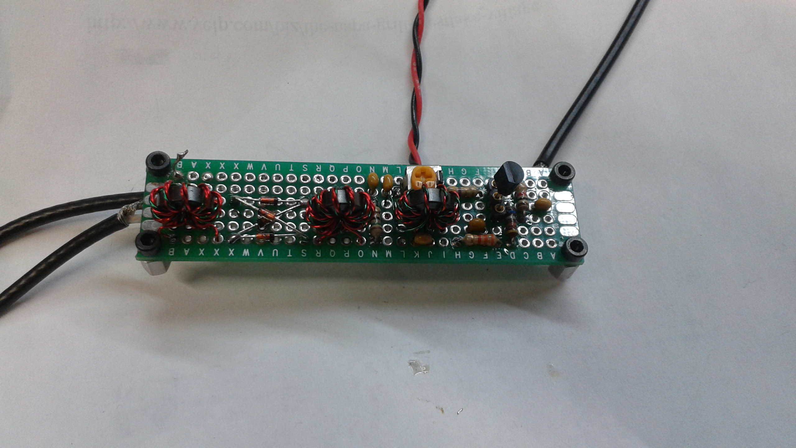
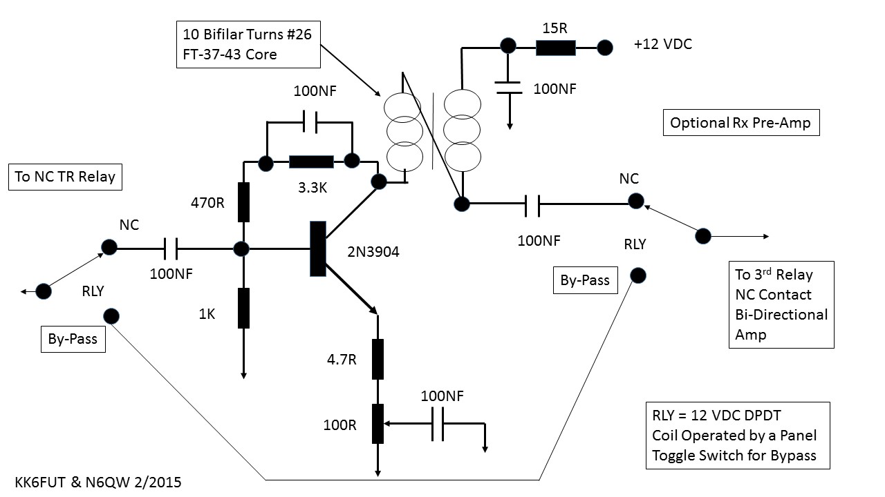
* Rx Tx Bi-directional Amplifier
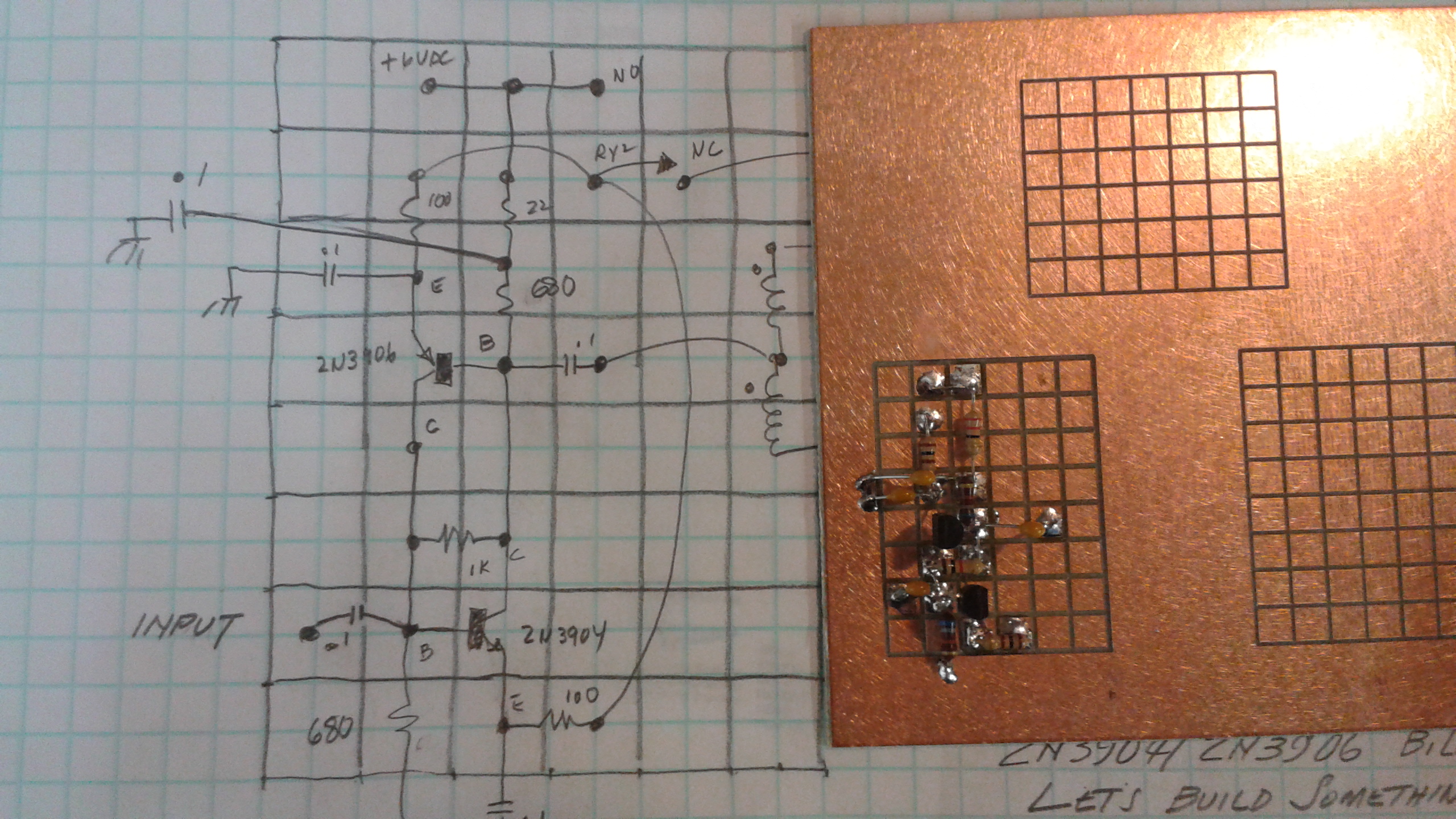
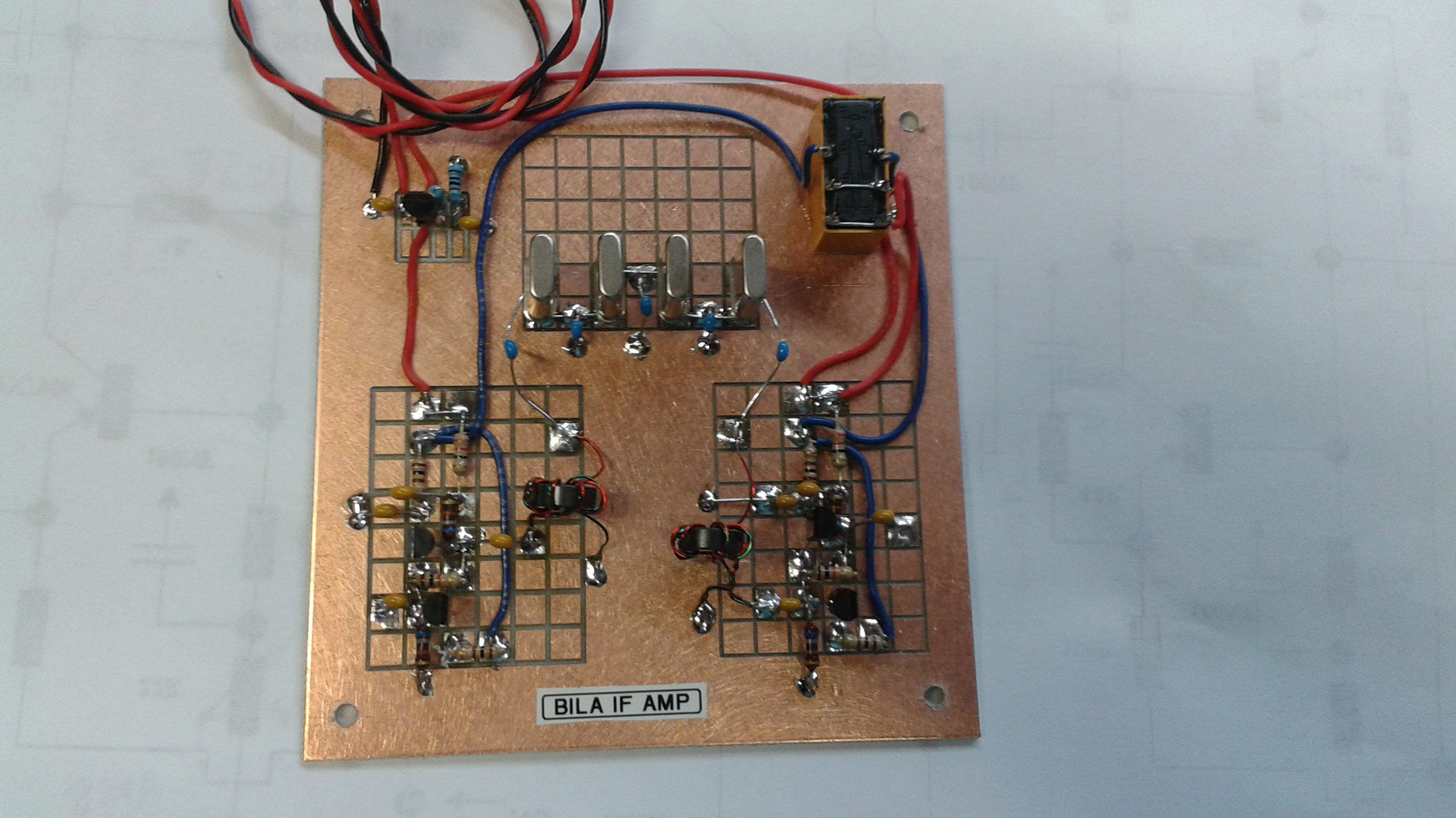
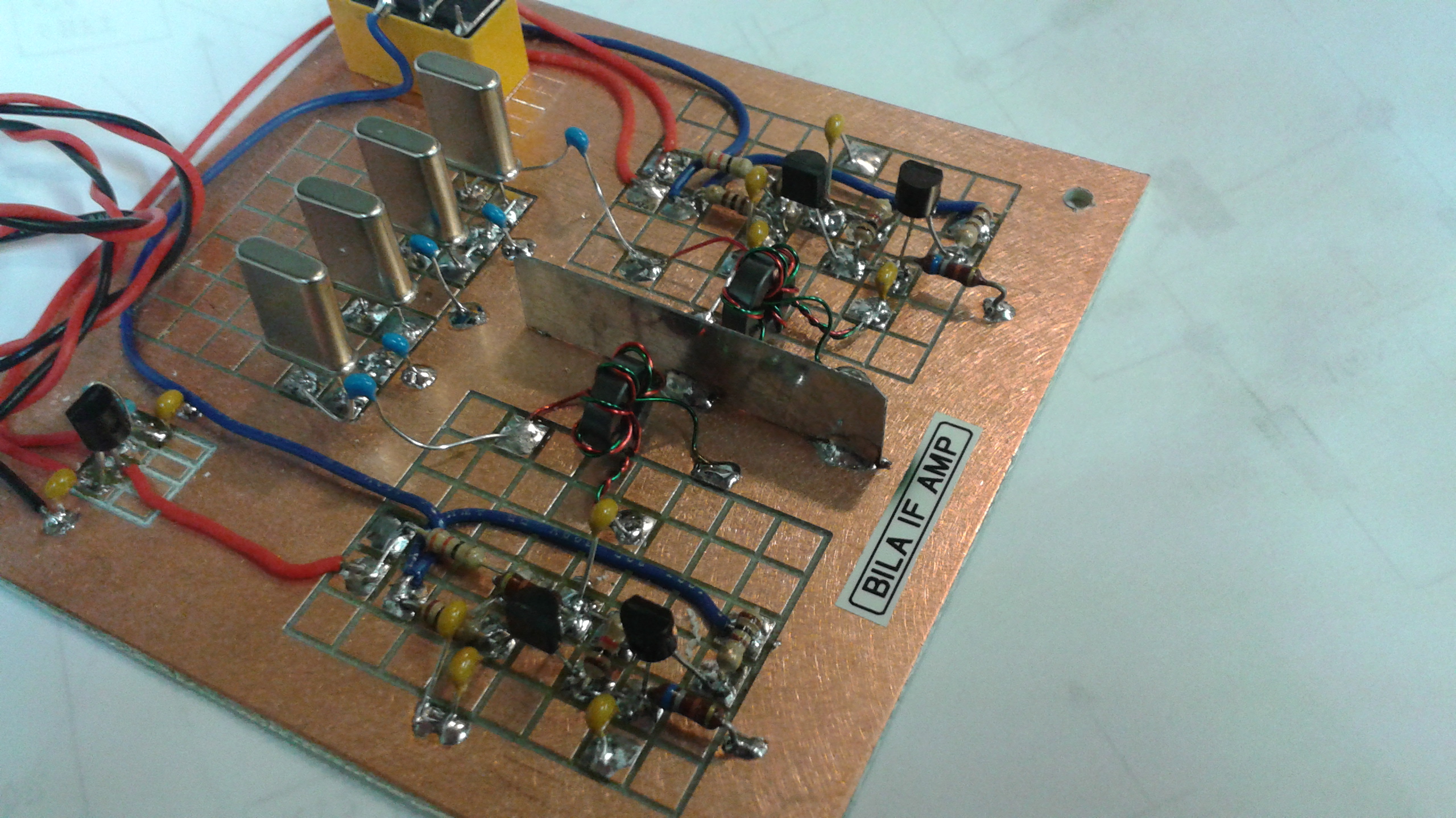
[Note: We understand that Mouser no longer is carrying the 42IF123 and thus the BPF must be built from discrete components. See the link above. Here is an alternate source from Kits & Parts.] * Bilateral Amplifier/Filter Schematic * Bilateral Amp Part Layout on MePads Link to Photo ------------------------Link to Photo ------------------LLink to Photo [Note in the last photo the shield between the bilateral amplfiers to prevent unwanted coupling, between the stages. The size of this board is 4" X 4 ".]
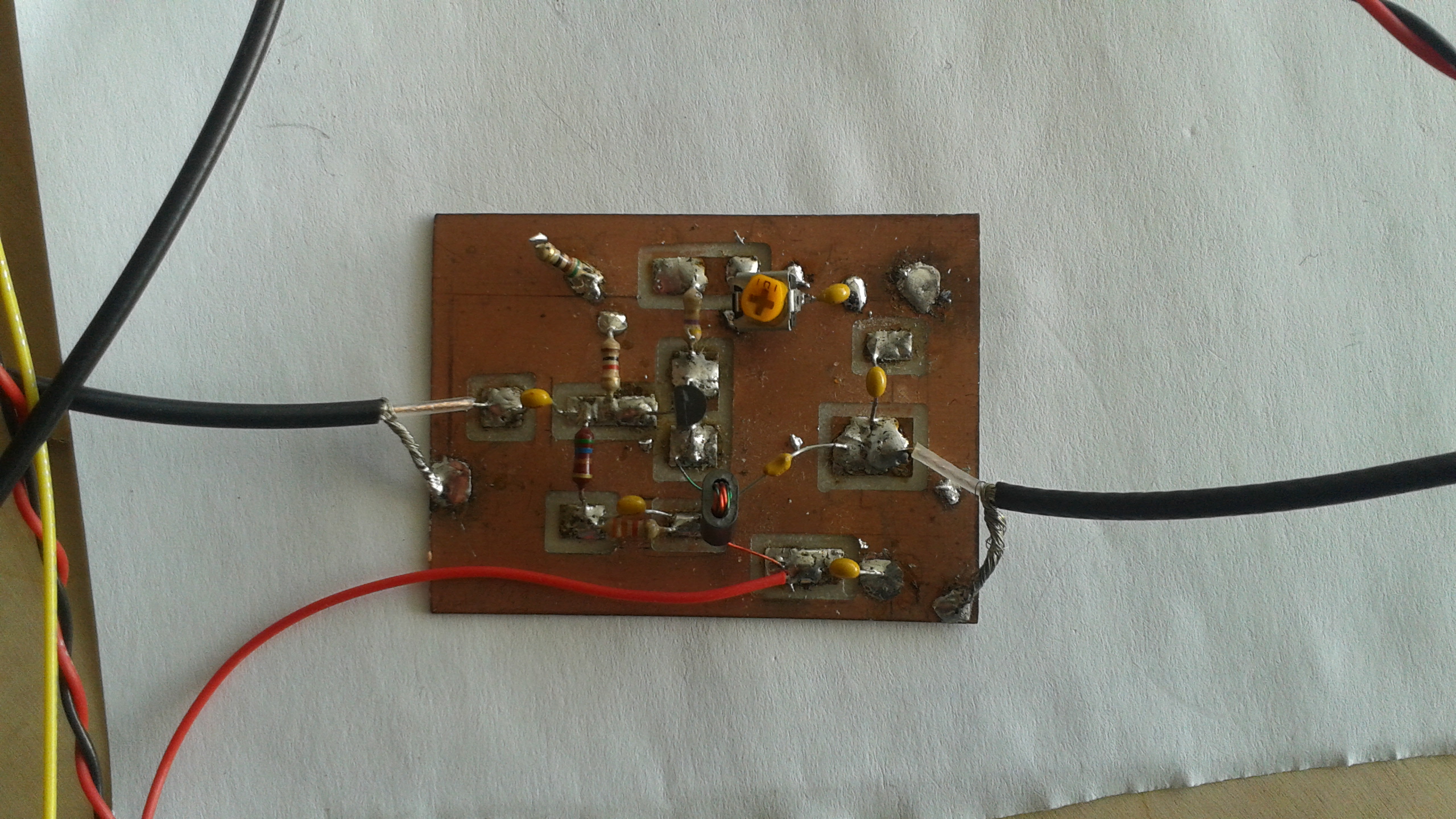
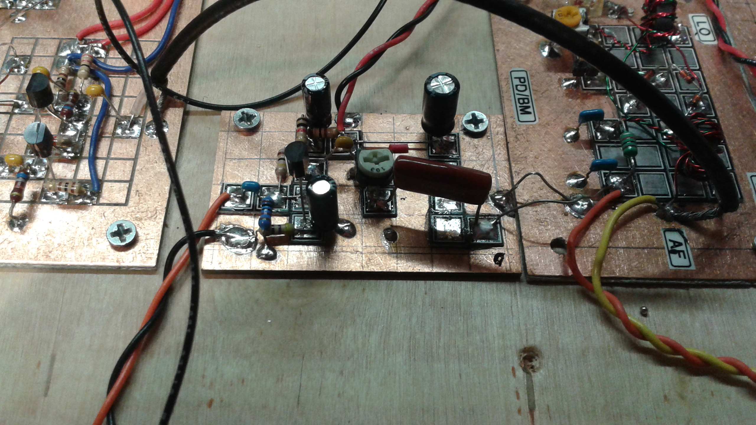
Note in the photo above of how the output of the Microphone Amplifier is in parallel with the input wiring that is routed to the Audio Amplifier stage. The circuits are isolated by capacitors and further isolation is provided by the fact that when one is on the other is off. That said a way to test the Microphone Amp is to power both "on" at the same time being careful to have the gain of both stages set very low. If you can hear your voice from the speaker when talking into the microphone then you have affirmed the Microphone amp is functioning properly . Link to Photo Note this is now just a single 2N3904 stage (see schematic). * Receiver / Transmitter Mixer Stage
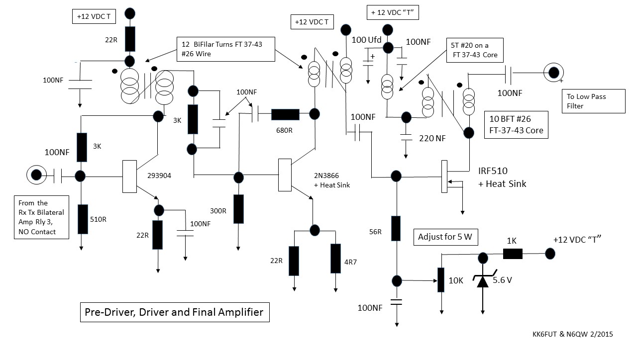
* Transmitter Pre-Driver, Driver and Final Amp R1 Adds 100 UFd Cap in the supply to the IRF510 |
|---|